
Designing the Charging Port Area Around a GB/T Combo Vehicle Inlet
 2026-10-29

The charging port area is a small part of an electric vehicle, but its design affects everyday usability, component installation, cable routing, and the overall reliability of the charging interface. For vehicle manufacturers, integrating a GB/T Combo Vehicle Inlet is not simply a matter of making the connector fit into a body panel. The surrounding structure must provide sufficient space for electrical connections, allow convenient access for charging, and support the requirements of vehicle assembly and testing.
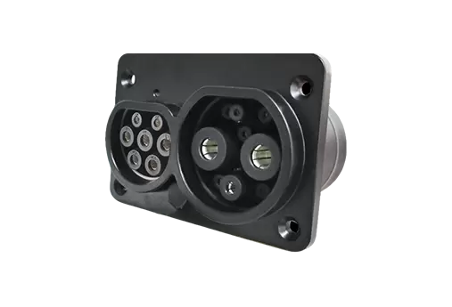
The GB/T Combo Vehicle Inlet (DC Input: 80A/125A/200A/250A) from DUOSIDA provides several current-rating options for electric vehicle projects. When incorporating this type of inlet into a new vehicle platform, engineers should consider the interface itself alongside the charging-port door, mounting structure, cable routing, protective cover, and nearby components.
This article examines the practical design decisions that can help vehicle manufacturers integrate a GB/T Combo Vehicle Inlet into a well-planned charging port area.
1. Start with the Vehicle Layout, Not Just the Inlet Dimensions
The first step in charging-port design is identifying where the inlet can be installed within the vehicle body. The front fender, rear quarter panel, front grille area, or another designated position may be considered, depending on the vehicle platform and its overall layout.
The final position should be determined by vehicle architecture rather than appearance alone.
Before fixing the mounting location, the design team should review:
Available space behind the exterior body panel.
Distance from the inlet to the relevant electrical components.
Potential interference with structural members and nearby equipment.
Access for installation, inspection, and maintenance.
The driver's ability to approach and connect the charging plug.
These checks are particularly important when the vehicle platform is still under development. Moving an inlet later in the design process can affect body-panel tooling, cable length, brackets, and assembly procedures.
The supplier's dimensional drawings should therefore be reviewed alongside the vehicle's three-dimensional packaging model. Engineers should confirm not only the external dimensions but also the space required behind the inlet for terminals, cable bends, connectors, and assembly tools.
2. Plan the Charging-Port Opening and Mounting Structure
A charging inlet must be securely mounted while remaining accessible to the user. The surrounding body structure needs to support the inlet without creating unnecessary installation difficulties.
For the DUOSIDA GB/T Combo Vehicle Inlet, the product information identifies a front-mounted installation arrangement. This makes the mounting interface and front-panel layout important items to confirm during vehicle integration.
The engineering team should check the mounting-hole positions, panel opening, required clearances, and the relationship between the inlet face and the surrounding bodywork.
A poorly planned opening can create several practical problems. The inlet may be difficult to install, the charging connector may be obstructed by the panel, or the protective cover may not operate as intended. Even a small interference issue can complicate production assembly.
It is also worth considering how the mounting arrangement will be inspected after installation. If technicians cannot easily access the relevant fasteners or connections, maintenance may require additional disassembly.
A useful approach is to evaluate the inlet and its mounting bracket as one assembly. This helps engineers identify possible interference before the body design is finalized.
3. Leave Enough Space for Cable Routing
The space behind the charging inlet deserves as much attention as the visible charging port.
Electrical cables need a suitable routing path from the inlet to the vehicle's charging system. The available space must accommodate the specified cable arrangement without excessive bending, twisting, or pressure on the terminals.
The cable configuration also depends on the selected inlet model. DUOSIDA lists DC input options of 80A, 125A, 200A, and 250A for this product, with AC options of 16A and 32A. Its model-selection information shows different cable specifications for different current configurations.
For example, the listed DC conductor specifications increase across the 80A, 125A, 200A, and 250A options. This illustrates why vehicle manufacturers should not finalize the mounting space using a generic cable assumption.
When reviewing the installation, engineers should consider three areas.
Bend radius and routing direction: The cable must follow the supplier's applicable bending requirements. A tight bend immediately behind the inlet can make installation difficult and place unnecessary stress on the connection.
Clearance from surrounding components: The routing path should avoid sharp edges, moving parts, and other areas where abrasion or interference may occur. Cable support should be considered where necessary.
Assembly access: The cable and terminal arrangement must allow technicians to complete the connection using the specified assembly process. A layout that works in a digital model may still be difficult to assemble in the actual vehicle.
These considerations should be reviewed for each selected current-rating configuration rather than assumed to be identical across the product range.
4. Design for Everyday Charging Access
A charging port should be straightforward to locate, open, connect, and close. This is a user-experience issue, but it also affects the physical design of the charging area.
The charging-port door should provide enough clearance for the charging plug and the user's hand. The connector should be easy to align with the inlet, and the surrounding bodywork should not obstruct insertion or removal.
The design team should evaluate the charging area in several conditions:
The charging plug is inserted and removed by a user.
The charging cable approaches from different practical directions.
The charging-port door is fully open.
The protective cover needs to be accessed.
The vehicle is parked close to a wall or another vehicle.
The last scenario is easy to overlook. A charging port may be technically accessible in an open test area but inconvenient when the vehicle is parked in a typical garage or public charging space.
A physical mock-up can help reveal these issues before the design enters production. Engineers can use it to check hand clearance, connector handling, door movement, and visibility of the inlet.
The objective is to make charging intuitive without compromising the available space for the electrical components.
5. Account for the Protective Cover and Environmental Exposure
The charging-port area is exposed to conditions that are different from those inside the vehicle. Rain, dust, road contamination, temperature changes, and repeated user interaction may affect the surrounding design.
The protective cover is therefore an important part of the integration review. DUOSIDA's product information identifies a protective-cover arrangement and lists IP54 and IP55 protection levels under working conditions. The precise protection conditions should be confirmed against the applicable product documentation before the vehicle design is approved.
Vehicle manufacturers should establish how the inlet will be protected when it is not connected to charging equipment. The charging-port door, protective cover, surrounding seals, and drainage provisions should be reviewed as a coordinated arrangement.
Several questions deserve attention:
Can the cover be accessed and operated without interference?
Does the body-panel design allow the intended protective arrangement to work correctly?
Could water or debris collect around the opening?
Are the sealing interfaces consistent with the supplier's installation requirements?
Can the area be inspected and cleaned during vehicle maintenance?
The inlet's declared protection rating should not be treated as a substitute for evaluating the complete vehicle installation. The surrounding panel, sealing arrangement, and installation conditions can influence the performance of the assembled charging-port area.
6. Check Thermal and Electrical Requirements During Packaging
Although the charging port is often designed as part of the exterior body, the inlet must also meet the vehicle's electrical and thermal requirements.
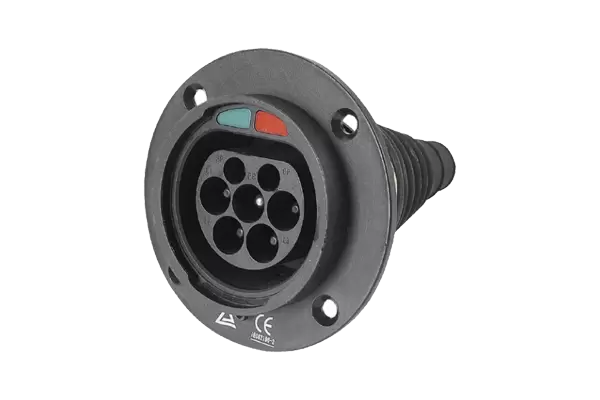
The DUOSIDA product page lists a DC operating voltage of 1000V, an AC operating voltage of 250V, and a terminal temperature rise of less than 50K under the stated test conditions. It also lists a contact resistance of up to 0.5 mΩ and an operating temperature range of -30°C to +50°C.
These published values provide useful reference points for initial engineering review. However, they should be interpreted according to the applicable test conditions and the specific model being considered.
For the vehicle design team, the practical task is to confirm that the selected inlet, its cables, and the surrounding installation are appropriate for the intended operating conditions.
The packaging review should consider heat sources near the charging port, the routing of power cables, and the space available for the specified cable configuration. Where the vehicle's duty cycle or operating environment introduces additional requirements, those requirements should be addressed in the system-level validation plan.
The inlet should not be selected based on current rating alone. The complete electrical design must be reviewed as a system.
7. Validate the Installation Before Production
Once the charging-port layout has been developed, the design should be checked through a combination of dimensional review, assembly trials, and applicable electrical and environmental tests.
A practical validation process can include:
Dimensional verification: Confirm the mounting opening, fixing points, clearances, and alignment between the inlet and body panel.
Assembly assessment: Install the inlet and its associated cables using the intended production procedure. Check whether technicians have sufficient access to complete the work.
Charging-access checks: Verify that the connector can be inserted and removed without interference from the body panel, door, or nearby components.
Protective-cover review: Confirm that the cover and surrounding sealing arrangement operate as intended in the installed configuration.
Electrical and environmental validation: Follow the applicable product specifications, vehicle requirements, and relevant standards. Testing should reflect the actual installation rather than relying only on component-level documentation.
DUOSIDA's product information also lists a mechanical life of more than 10,000 no-load insertion and withdrawal cycles. Vehicle manufacturers should confirm the applicable test method and model configuration when using this information in their qualification process.
Finding an interference issue or an assembly difficulty during prototype validation is generally easier to address than discovering it after production tooling and assembly procedures have been finalized.
8. Work with a Supplier That Can Support Vehicle Integration
The quality of the charging-port design depends partly on the technical information available during development. A supplier should be able to clarify product configurations, dimensional requirements, cable specifications, and relevant test documentation.
Zhangjiagang UCHEN New Energy Technology Co., Ltd., known as Youcheng Technology (stock code: 873087), focuses on the development and market promotion of high-performance charging products for new energy vehicles.
Through the DUOSIDA official website, vehicle manufacturers and component buyers can explore products across several EV charging categories, including charging sockets, charging plugs, high-power charging products, NACS products, vehicle outlet sockets, and high-voltage connectors.
For projects using China's GB/T charging interface, the GB/T Combo Vehicle Inlet with DC input options from 80A to 250A is a relevant product to review during early design planning.
When contacting the supplier, provide the intended current rating, vehicle installation location, available packaging space, cable-routing requirements, and project validation needs. Sharing these details helps establish whether the proposed configuration matches the vehicle's design requirements.
Conclusion
Designing the charging-port area around a GB/T Combo Vehicle Inlet requires coordination between vehicle packaging, electrical engineering, body design, and manufacturing. The inlet must fit the available space, provide practical charging access, accommodate the specified cables, and work with the vehicle's protective and sealing arrangements.
The most effective approach is to evaluate the charging port as a complete installed assembly rather than as an isolated component. By checking dimensions early, confirming the selected model's technical data, and validating the physical installation before production, EV manufacturers can reduce avoidable design changes and create a charging interface that is easier to assemble and use.